CPS Analysis - Co-simulation, Design Space Exploration and Model Checking/Test Automation
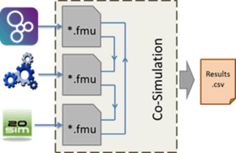
A Co-Simulation orchestration engine (COE) has been created that organises the exchange of simulation results between the single models. Figure 1 shows a simplified scheme of the interaction. The single modelling tools export their models as encapsulated files in the Functional Mock-up Unit (FMU), following the Functional Mock-up Interface (FMI) standard.
Within INTO-CPS, the modelling tools Overture (www.overturetool.org), OpenModelica (www.openmodelica.org) and 20-sim (www.20sim.com) are used. Since the Co-simulation engine is fully FMI compliant, any FMU that supports the FMI standard can be used as well. The signals that are exchanged between the Co-simulation are saved to file. The Co-simulation engine is Java based and can therefore be used on Windows, Linux and Mac platforms (32-bit and 64-bit).
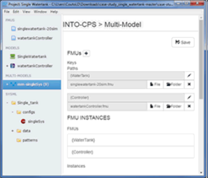
In addition, a user interface was created that aims at easy setup of co-simulation projects. The user interface allows for easy configuration of the co-simulation, selection of models, setting of parameters and view of results. The configuration, which describes the signals that are being exchanged between the different models (e.g. the FMUs), can be derived from the SysML model that is created by the Modelio tool.
The user interface also provides extensibility with other features, such as design space exploration, test automation or traceability.
In the process of developing complex systems, such as Cyber-Physical Systems, many design decisions must be made. Some of the parameters are hard to determine initially, and experimental tests may not yet be possible in an early design phase. To speed up this process, Design Space Exploration (DSE) is a suitable method for optimizing system behaviour based on simulations.
We developed methods for DSE that allow optimization of design parameters to reach desired system behaviour. This comprises as a first step the definition of the variable parameters and their bounds and determination of the target values that should be optimized. In the next step, one of multiple available algorithms for sweeping the parameter space can be selected. Finally, the Co-simulation is initialized and the simulation runs start. Finally the results are presented in a meaningful way. In addition to single parameters, alternative designs that consist of different system parts can also be compared.
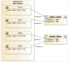
In the context of INTO-CPS, DSE has multiple connections. On the SysML level, different diagrams have been designed to derive the DSE parameters and target values from the existing system model. These diagrams were implemented in Modelio.
Figure 3 shows an example of the DSE Parameter Connection Diagram in SysML, where the SysML elements (the sensors and their position) are related with boundary values for a DSE analysis.
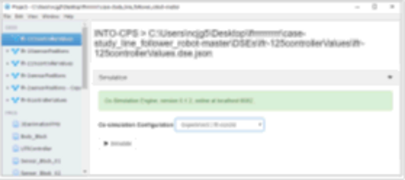
The algorithms have been implemented into the INTO-CPS application (see Figure 2) to give the user a coherent and easy-to-use interface. Figure 4 shows how a DSE analysis can be configured and launched from within the INTO-CPS application.
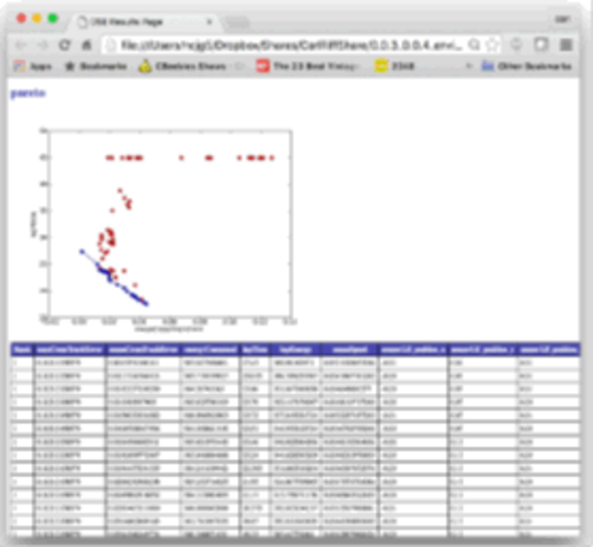
The results from such a DSE analysis can then be shown in a web browser, e.g. as a Pareto front that shows the best trade-off between two goals (see Figure 5). This can help the designers in optimizing the system behaviour already in a rather early design phase. Finally, methods to execute the DSE runs on a cloud are being investigated to allow users with limited computing power to benefit from DSE too.
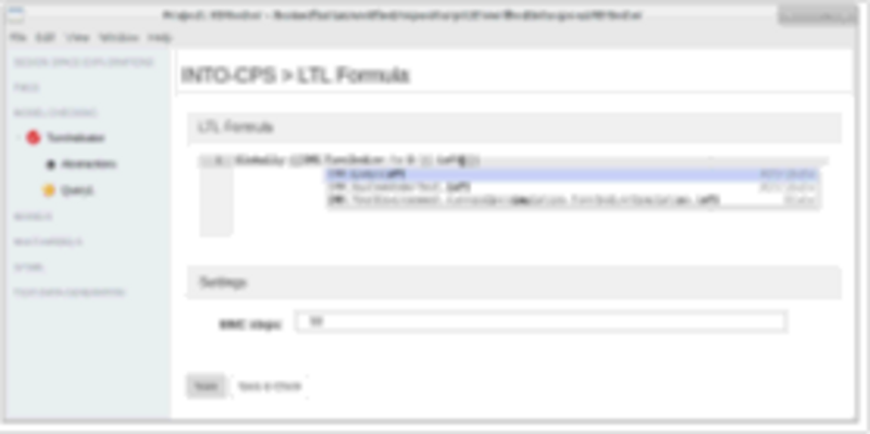
In the design process of CPSs, engineers need to make sure that the actual system behaviour is fulfilling the requirements. One approach to do so is Model Checking, where the system under test is exhaustively checked against certain requirements. These requirements must be defined in a logical formalism. Here, Linear Temporal Logic (LTL) has been chosen to define the requirements. The model that is being checked can either be a discrete event (DE) model, or a continuous time (CT) model.
Model checking is using the RT Tester tool-suite from Verified Systems (www.verified.com). Using the model checking capabilities is integrated in the INTO-CPS application (see Figure 6) to give the user a coherent workflow and interface.
The model checker then examines the system under test in a limited number of steps. If no example can be found within the defined number of steps that contradicts the requirements, the example has passed the check. Otherwise, the model checker returns a counterexample. This helps the engineers validating the desired system behaviour.