CPS Architectural and Simulation Modelling and Traceability
The architectural modelling of a CPS is the most abstract description of the system. It defines the major elements of the CPS with its most important properties, such as signals being exchanged between the elements. These signals can be physical in nature, such as flow of media or forces, or logical, such as information. In addition, the blocks are described by parameters which can be design parameters.
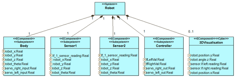
The architectural modelling then describes the hierarchy of the system's components. It allows decomposition of a complex system into sub-systems or components. In INTO-CPS, the architecture is being modelled in SysML using a profile that specialises SysML to the case of a CPS. Such a simple architecture of the system "Robot" is shown in the following figure. It is important to note that the architecture is not meant to be static, but to evolve over the development of a CPS.
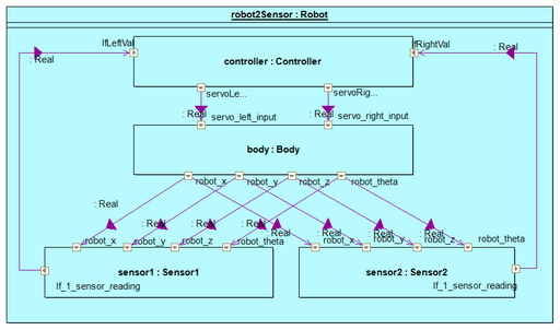
Based on the architecture, a simulation model can be described by a connections diagram, shown in the figure below. This connections diagram is also made in SysML, again using the profile. Each block in the diagram corresponds to one model with parameters and signals going in or out of the model.
The connections diagram can then be exported to a co-simulation configuration, which can seamlessly be used by the INTO-CPS co-Simulation.
Like the architectural model of a CPS, the simulation model is not static and will most likely evolve over the development cycle of a CPS, for example when models have additional parameters or connections change.
In INTO-CPS, architectural and simulation modelling are done in the Modelio software tool (www.modelio.org).
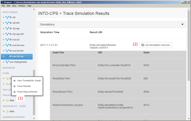
To master the complexity of different models, simulation results, test cases and all the other files that are being generated over the course of a CPS's development cycle, INTO-CPS offers support for traceability. This means that all the tools send information of generated or modified files (such as requirements that are created, connections diagrams that are exported, or FMUs that are compiled) to a central database. The user can then query the database for the connections between the different artifacts. For example, the user can reconstruct from which FMU versions a simulation result was created. This is integrated into the INTO-CPS application and shown in the following figure.
WANT TO LEARN MORE
Take a look at the following project deliverable: